Tuesday, November 12, 2019
Tuesday, October 15, 2019
Steps to create VHDL project in Xilinx


Steps to create VHDL module:


Steps to create VHDL test bench:


Monday, October 14, 2019
Types of Shift Register
Note: Consider all Images with Negative edge triggering and update in your diagram accordingly.
SISO:

SIPO:

PISO:

PIPO:

Monday, September 23, 2019
Write VHDL code for 3 bit Asynchronous up counter using Structural modeling
library IEEE;
use IEEE.STD_LOGIC_1164.ALL;
entity jk_ff is
Port ( j : in STD_LOGIC;
k : in STD_LOGIC;
clock : in STD_LOGIC;
reset : in STD_LOGIC;
q : out STD_LOGIC);
end jk_ff;
architecture Behavioral of jk_ff is
signal jk : std_logic_vector(1 downto 0) := "00";
signal qsig : std_logic := '0';
begin
jk <= j & k;
process(reset,clock)
begin
if (reset = '1')then
qsig <='0';
elsif (clock'event and clock = '1')then
case (jk) is
when "00" => qsig <= qsig;
when "01" => qsig <= '0';
when "10" => qsig <= '1';
when others => qsig <= not qsig;
end case;
end if;
end process;
q <= qsig;
end Behavioral;
--Step2. VHDL code for 3 bit Counter using structural modeling
library IEEE;
use IEEE.STD_LOGIC_1164.ALL;
entity counter_test is
Port ( clock : in STD_LOGIC;
reset : in STD_LOGIC;
count : out STD_LOGIC_VECTOR (2 downto 0));
end counter_test;
architecture structural_test of counter_test is
component jk_ff is
Port ( j : in STD_LOGIC;
k : in STD_LOGIC;
clock : in STD_LOGIC;
reset : in STD_LOGIC;
q : out STD_LOGIC);
end component;
signal temp:std_logic_vector(2 downto 0) := "000";
begin
label1 : jk_ffport map ( reset => reset, clock => clock, j => '1', k => '1', q => temp(2));
label2 : jk_ff port map (reset => reset,clock =>NOT temp(2), j => '1', k => '1', q => temp(1));
label3 : jk_ff port map ( reset => reset,clock => NOT temp(1), j => '1', k => '1',q => temp(0));
count(2) <= temp(0);
count(1) <= temp(1);
count(0) <= temp(2);
end structural_test;
--Step3. Test Bench Code
LIBRARY ieee;
USE ieee.std_logic_1164.ALL;
ENTITY tb_test1 IS
END tb_test1;
ARCHITECTURE behavior OF tb_test1 IS
COMPONENT counter_test
PORT(
clock : IN std_logic;
reset : IN std_logic;
count : OUT std_logic_vector(2 downto 0)
);
END COMPONENT;
--Inputs
signal clock : std_logic := '0';
signal reset : std_logic := '0';
--Outputs
signal count : std_logic_vector(2 downto 0);
BEGIN
-- Instantiate the Unit Under Test (UUT)
uut: counter_test PORT MAP (
clock => clock,
reset => reset,
count => count
);
process
begin
wait for 5ns;
clock <= not clock;
end process;
process
begin
reset <= '1';
wait for 50ns;
reset <= not reset;
wait;
end process;
END;
use IEEE.STD_LOGIC_1164.ALL;
entity jk_ff is
Port ( j : in STD_LOGIC;
k : in STD_LOGIC;
clock : in STD_LOGIC;
reset : in STD_LOGIC;
q : out STD_LOGIC);
end jk_ff;
architecture Behavioral of jk_ff is
signal jk : std_logic_vector(1 downto 0) := "00";
signal qsig : std_logic := '0';
begin
jk <= j & k;
process(reset,clock)
begin
if (reset = '1')then
qsig <='0';
elsif (clock'event and clock = '1')then
case (jk) is
when "00" => qsig <= qsig;
when "01" => qsig <= '0';
when "10" => qsig <= '1';
when others => qsig <= not qsig;
end case;
end if;
end process;
q <= qsig;
end Behavioral;
--Step2. VHDL code for 3 bit Counter using structural modeling
library IEEE;
use IEEE.STD_LOGIC_1164.ALL;
entity counter_test is
Port ( clock : in STD_LOGIC;
reset : in STD_LOGIC;
count : out STD_LOGIC_VECTOR (2 downto 0));
end counter_test;
architecture structural_test of counter_test is
component jk_ff is
Port ( j : in STD_LOGIC;
k : in STD_LOGIC;
clock : in STD_LOGIC;
reset : in STD_LOGIC;
q : out STD_LOGIC);
end component;
signal temp:std_logic_vector(2 downto 0) := "000";
begin
label1 : jk_ffport map ( reset => reset, clock => clock, j => '1', k => '1', q => temp(2));
label2 : jk_ff port map (reset => reset,clock =>NOT temp(2), j => '1', k => '1', q => temp(1));
label3 : jk_ff port map ( reset => reset,clock => NOT temp(1), j => '1', k => '1',q => temp(0));
count(2) <= temp(0);
count(1) <= temp(1);
count(0) <= temp(2);
end structural_test;
--Step3. Test Bench Code
LIBRARY ieee;
USE ieee.std_logic_1164.ALL;
ENTITY tb_test1 IS
END tb_test1;
ARCHITECTURE behavior OF tb_test1 IS
COMPONENT counter_test
PORT(
clock : IN std_logic;
reset : IN std_logic;
count : OUT std_logic_vector(2 downto 0)
);
END COMPONENT;
--Inputs
signal clock : std_logic := '0';
signal reset : std_logic := '0';
--Outputs
signal count : std_logic_vector(2 downto 0);
BEGIN
-- Instantiate the Unit Under Test (UUT)
uut: counter_test PORT MAP (
clock => clock,
reset => reset,
count => count
);
process
begin
wait for 5ns;
clock <= not clock;
end process;
process
begin
reset <= '1';
wait for 50ns;
reset <= not reset;
wait;
end process;
END;
Sunday, September 22, 2019
Write VHDL code for Half Adder using Behavioral modeling
library IEEE;
use IEEE.STD_LOGIC_1164.ALL;
entity ha is
Port ( a : in STD_LOGIC;
b : in STD_LOGIC;
sum : out STD_LOGIC;
cout : out STD_LOGIC);
end ha;
architecture Behavioral of ha is
begin
process(a,b)
begin
if(a = '0' AND b ='0') then
sum <= '0';
cout <= '0';
elsif(a = '0' AND b ='1') then
sum <= '1';
cout <= '0';
elsif(a = '1' AND b ='0') then
sum <= '1';
cout <= '0';
else
sum <= '0';
cout <= '1';
end if;
end process;
end Behavioral;
Write VHDL code for Half Adder using Data Flow Modeling
library IEEE;
use IEEE.STD_LOGIC_1164.ALL;
entity test_HA is
Port ( a : in STD_LOGIC;
b : in STD_LOGIC;
sum : out STD_LOGIC;
cout : out STD_LOGIC);
end test_HA;
architecture data_flow_test of test_HA is
begin
sum<= a xor b;
cout<= a and b;
end data_flow_test;
use IEEE.STD_LOGIC_1164.ALL;
entity test_HA is
Port ( a : in STD_LOGIC;
b : in STD_LOGIC;
sum : out STD_LOGIC;
cout : out STD_LOGIC);
end test_HA;
architecture data_flow_test of test_HA is
begin
sum<= a xor b;
cout<= a and b;
end data_flow_test;
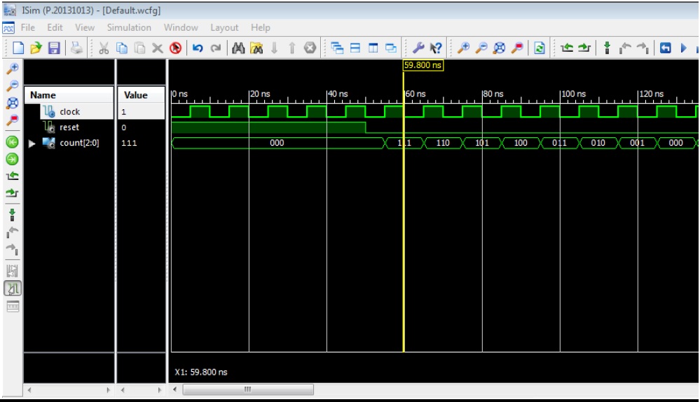
Write VHDL code for 3 bit Asynchronous down counter using Structural modeling
--Step1. VHDL code for JK-FF
library IEEE;
use IEEE.STD_LOGIC_1164.ALL;
entity jk_ff is
Port ( j : in STD_LOGIC;
k : in STD_LOGIC;
clock : in STD_LOGIC;
reset : in STD_LOGIC;
q : out STD_LOGIC);
end jk_ff;
architecture Behavioral of jk_ff is
signal jk : std_logic_vector(1 downto 0) := "00";
signal qsig : std_logic := '0';
begin
jk <= j & k;
process(reset,clock)
begin
if (reset = '1')then
qsig <='0';
elsif (clock'event and clock = '1')then
case (jk) is
when "00" => qsig <= qsig;
when "01" => qsig <= '0';
when "10" => qsig <= '1';
when others => qsig <= not qsig;
end case;
end if;
end process;
q <= qsig;
end Behavioral;
--Step2. VHDL code for 3 bit Counter using structural modeling
library IEEE;
use IEEE.STD_LOGIC_1164.ALL;
entity counter_test is
Port ( clock : in STD_LOGIC;
reset : in STD_LOGIC;
count : out STD_LOGIC_VECTOR (2 downto 0));
end counter_test;
architecture structural_test of counter_test is
component jk_ff is
Port ( j : in STD_LOGIC;
k : in STD_LOGIC;
clock : in STD_LOGIC;
reset : in STD_LOGIC;
q : out STD_LOGIC);
end component;
signal temp:std_logic_vector(2 downto 0) := "000";
begin
label1 : jk_ff
port map ( reset => reset, clock => clock, j => '1', k => '1', q => temp(2));
label2 : jk_ff port map (reset => reset,clock => temp(2), j => '1', k => '1', q => temp(1));
label3 : jk_ff port map ( reset => reset,clock => temp(1), j => '1', k => '1',q => temp(0));
count(2) <= temp(0);
count(1) <= temp(1);
count(0) <= temp(2);
end structural_test;
--Step3. Test Bench Code
LIBRARY ieee;
USE ieee.std_logic_1164.ALL;
ENTITY tb_test1 IS
END tb_test1;
ARCHITECTURE behavior OF tb_test1 IS
COMPONENT counter_test
PORT(
clock : IN std_logic;
reset : IN std_logic;
count : OUT std_logic_vector(2 downto 0)
);
END COMPONENT;
--Inputs
signal clock : std_logic := '0';
signal reset : std_logic := '0';
--Outputs
signal count : std_logic_vector(2 downto 0);
BEGIN
-- Instantiate the Unit Under Test (UUT)
uut: counter_test PORT MAP (
clock => clock,
reset => reset,
count => count
);
process
begin
wait for 5ns;
clock <= not clock;
end process;
process
begin
reset <= '1';
wait for 50ns;
reset <= not reset;
wait;
end process;
END;
OUTPUT:

library IEEE;
use IEEE.STD_LOGIC_1164.ALL;
entity jk_ff is
Port ( j : in STD_LOGIC;
k : in STD_LOGIC;
clock : in STD_LOGIC;
reset : in STD_LOGIC;
q : out STD_LOGIC);
end jk_ff;
architecture Behavioral of jk_ff is
signal jk : std_logic_vector(1 downto 0) := "00";
signal qsig : std_logic := '0';
begin
jk <= j & k;
process(reset,clock)
begin
if (reset = '1')then
qsig <='0';
elsif (clock'event and clock = '1')then
case (jk) is
when "00" => qsig <= qsig;
when "01" => qsig <= '0';
when "10" => qsig <= '1';
when others => qsig <= not qsig;
end case;
end if;
end process;
q <= qsig;
end Behavioral;
--Step2. VHDL code for 3 bit Counter using structural modeling
library IEEE;
use IEEE.STD_LOGIC_1164.ALL;
entity counter_test is
Port ( clock : in STD_LOGIC;
reset : in STD_LOGIC;
count : out STD_LOGIC_VECTOR (2 downto 0));
end counter_test;
architecture structural_test of counter_test is
component jk_ff is
Port ( j : in STD_LOGIC;
k : in STD_LOGIC;
clock : in STD_LOGIC;
reset : in STD_LOGIC;
q : out STD_LOGIC);
end component;
signal temp:std_logic_vector(2 downto 0) := "000";
begin
label1 : jk_ff
port map ( reset => reset, clock => clock, j => '1', k => '1', q => temp(2));
label2 : jk_ff port map (reset => reset,clock => temp(2), j => '1', k => '1', q => temp(1));
label3 : jk_ff port map ( reset => reset,clock => temp(1), j => '1', k => '1',q => temp(0));
count(2) <= temp(0);
count(1) <= temp(1);
count(0) <= temp(2);
end structural_test;
--Step3. Test Bench Code
LIBRARY ieee;
USE ieee.std_logic_1164.ALL;
ENTITY tb_test1 IS
END tb_test1;
ARCHITECTURE behavior OF tb_test1 IS
COMPONENT counter_test
PORT(
clock : IN std_logic;
reset : IN std_logic;
count : OUT std_logic_vector(2 downto 0)
);
END COMPONENT;
--Inputs
signal clock : std_logic := '0';
signal reset : std_logic := '0';
--Outputs
signal count : std_logic_vector(2 downto 0);
BEGIN
-- Instantiate the Unit Under Test (UUT)
uut: counter_test PORT MAP (
clock => clock,
reset => reset,
count => count
);
process
begin
wait for 5ns;
clock <= not clock;
end process;
process
begin
reset <= '1';
wait for 50ns;
reset <= not reset;
wait;
end process;
END;
OUTPUT:
Write VHDL code for 4:1 MUX
library IEEE;
use IEEE.STD_LOGIC_1164.all;
entity mux_test is
port(
A,B,C,D : in STD_LOGIC;
S0,S1: in STD_LOGIC;
Z: out STD_LOGIC
);
end mux_test;
architecture beh_test of mux_test is
begin
process (A,B,C,D,S0,S1) is
begin
if (S0 ='0' and S1 = '0') then
Z <= A;
elsif (S0 ='1' and S1 = '0') then
Z <= B;
elsif (S0 ='0' and S1 = '1') then
Z <= C;
else
Z <= D;
end if;
end process;
end beh_test;
Test Bench Code for 4 to 1 Multiplexer:
LIBRARY ieee;
USE ieee.std_logic_1164.ALL;
ENTITY tb_mux_test IS
END tb_mux_test;
ARCHITECTURE behavior OF tb_mux_test IS
-- Component Declaration for the Unit Under Test (UUT)
COMPONENT mux_test
PORT(
A : IN std_logic;
B : IN std_logic;
C : IN std_logic;
D : IN std_logic;
S0 : IN std_logic;
S1 : IN std_logic;
Z : OUT std_logic
);
END COMPONENT;
--Inputs
signal A : std_logic := '0';
signal B : std_logic := '0';
signal C : std_logic := '0';
signal D : std_logic := '0';
signal S0 : std_logic := '0';
signal S1 : std_logic := '0';
--Outputs
signal Z : std_logic;
BEGIN
uut: mux_test PORT MAP (
A => A,
B => B,
C => C,
D => D,
S0 => S0,
S1 => S1,
Z => Z
);
process
begin
wait for 5 ns;
A <= '1';
B <= '0';
C <= '1';
D <= '0';
S0 <= '0'; S1 <= '0';
wait for 10 ns;
S0 <= '0'; S1 <= '1';
wait for 10 ns;
S0 <= '1'; S1 <= '0';
wait for 10 ns;
S0 <= '1'; S1 <= '1';
wait for 10 ns;
end process;
END;
OUTPUT:

Write VHDL code for JK Flip Flop
library IEEE;
use IEEE.STD_LOGIC_1164.ALL;
entity jk_ff is
Port ( j : in STD_LOGIC;
k : in STD_LOGIC;
clock : in STD_LOGIC;
reset : in STD_LOGIC;
q : out STD_LOGIC);
end jk_ff;
architecture Behavioral of jk_ff is
signal jk : std_logic_vector(1 downto 0) := "00";
signal qsig : std_logic := '0';
begin
jk <= j & k;
process(reset,clock)
begin
if (reset = '1')then
qsig <='0';
elsif (clock'event and clock = '1')then
case (jk) is
when "00" => qsig <= qsig;
when "01" => qsig <= '0';
when "10" => qsig <= '1';
when others => qsig <= not qsig;
end case;
end if;
end process;
q <= qsig;
end Behavioral;
Write VHDL code for NOR gate
library IEEE;
use IEEE.STD_LOGIC_1164.ALL;
entity test_or is
Port ( p : in STD_LOGIC;
q : in STD_LOGIC;
r : out STD_LOGIC);
end test_or;
architecture data_flow_test of test_or is
begin
r<= p NOR q;
end data_flow_test;
use IEEE.STD_LOGIC_1164.ALL;
entity test_or is
Port ( p : in STD_LOGIC;
q : in STD_LOGIC;
r : out STD_LOGIC);
end test_or;
architecture data_flow_test of test_or is
begin
r<= p NOR q;
end data_flow_test;
Write VHDL code for NAND gate
library IEEE;
use IEEE.STD_LOGIC_1164.ALL;
entity test_or is
Port ( p : in STD_LOGIC;
q : in STD_LOGIC;
r : out STD_LOGIC);
end test_or;
architecture data_flow_test of test_or is
begin
r<= p NAND q;
end data_flow_test;
use IEEE.STD_LOGIC_1164.ALL;
entity test_or is
Port ( p : in STD_LOGIC;
q : in STD_LOGIC;
r : out STD_LOGIC);
end test_or;
architecture data_flow_test of test_or is
begin
r<= p NAND q;
end data_flow_test;
Write VHDL code XNOR gate
library IEEE;
use IEEE.STD_LOGIC_1164.ALL;
entity test_or is
Port ( p : in STD_LOGIC;
q : in STD_LOGIC;
r : out STD_LOGIC);
end test_or;
architecture data_flow_test of test_or is
begin
r<= p XNOR q;
end data_flow_test;
use IEEE.STD_LOGIC_1164.ALL;
entity test_or is
Port ( p : in STD_LOGIC;
q : in STD_LOGIC;
r : out STD_LOGIC);
end test_or;
architecture data_flow_test of test_or is
begin
r<= p XNOR q;
end data_flow_test;
Write VHDL code for XOR gate
library IEEE;
use IEEE.STD_LOGIC_1164.ALL;
entity test_or is
Port ( p : in STD_LOGIC;
q : in STD_LOGIC;
r : out STD_LOGIC);
end test_or;
architecture data_flow_test of test_or is
begin
r<= p XOR q;
end data_flow_test;
use IEEE.STD_LOGIC_1164.ALL;
entity test_or is
Port ( p : in STD_LOGIC;
q : in STD_LOGIC;
r : out STD_LOGIC);
end test_or;
architecture data_flow_test of test_or is
begin
r<= p XOR q;
end data_flow_test;
Write VHDL code for NOT gate
library IEEE;
use IEEE.STD_LOGIC_1164.ALL;
entity test_or is
Port ( p : in STD_LOGIC;
r : out STD_LOGIC);
end test_or;
architecture data_flow_test of test_or is
begin
r<= NOT q;
end data_flow_test;
use IEEE.STD_LOGIC_1164.ALL;
entity test_or is
Port ( p : in STD_LOGIC;
r : out STD_LOGIC);
end test_or;
architecture data_flow_test of test_or is
begin
r<= NOT q;
end data_flow_test;
Write VHDL code for AND gate
library IEEE;
use IEEE.STD_LOGIC_1164.ALL;
entity test_or is
Port ( p : in STD_LOGIC;
q : in STD_LOGIC;
r : out STD_LOGIC);
end test_or;
architecture data_flow_test of test_or is
begin
r<= p AND q;
end data_flow_test;
use IEEE.STD_LOGIC_1164.ALL;
entity test_or is
Port ( p : in STD_LOGIC;
q : in STD_LOGIC;
r : out STD_LOGIC);
end test_or;
architecture data_flow_test of test_or is
begin
r<= p AND q;
end data_flow_test;
Write VHDL code for OR gate
library IEEE;
use IEEE.STD_LOGIC_1164.ALL;
entity test_or is
Port ( p : in STD_LOGIC;
q : in STD_LOGIC;
r : out STD_LOGIC);
end test_or;
architecture data_flow_test of test_or is
begin
r<= p OR q;
end data_flow_test;
use IEEE.STD_LOGIC_1164.ALL;
entity test_or is
Port ( p : in STD_LOGIC;
q : in STD_LOGIC;
r : out STD_LOGIC);
end test_or;
architecture data_flow_test of test_or is
begin
r<= p OR q;
end data_flow_test;
Introduction to VHDL
VHDL stands for very high-speed integrated circuit hardware description language. It is a programming language used to model a digital system by dataflow, behavioral and structural style of modeling. This language was first introduced in 1981 for the department of Defense (DoD) under the VHSIC program.
Describing a Design
In VHDL an entity is used to describe a hardware module. An entity can be described using,
- Entity declaration
- Architecture
- Configuration
- Package declaration
- Package body
Entity Declaration
It defines the names, input output signals and modes of a hardware module.
Syntax −
entity entity_name is
   Port declaration;
end entity_name;
An entity declaration should start with ‘entity’ and end with ‘end’ keywords. The direction will be input, output or inout.
| In | Port can be read |
| Out | Port can be written |
| Inout | Port can be read and written |
| Buffer | Port can be read and written, it can have only one source. |
Architecture −
Architecture can be described using structural, dataflow, behavioral or mixed style.
Syntax −
architecture architecture_name of entity_name
architecture_declarative_part;

begin
   Statements;
end architecture_name;
Here, we should specify the entity name for which we are writing the architecture body. The architecture statements should be inside the ‘begin’ and ‘énd’ keyword. Architecture declarative part may contain variables, constants, or component declaration.
Data Flow Modeling
In this modeling style, the flow of data through the entity is expressed using concurrent (parallel) signal. The concurrent statements in VHDL are WHEN and GENERATE.
Besides them, assignments using only operators (AND, NOT, +, *, sll, etc.) can also be used to construct code.
Finally, a special kind of assignment, called BLOCK, can also be employed in this kind of code.
In concurrent code, the following can be used −
- Operators
- The WHEN statement (WHEN/ELSE or WITH/SELECT/WHEN);
- The GENERATE statement;
- The BLOCK statement
Behavioral Modeling
In this modeling style, the behavior of an entity as set of statements is executed sequentially in the specified order. Only statements placed inside a PROCESS, FUNCTION, or PROCEDURE are sequential.
PROCESSES, FUNCTIONS, and PROCEDURES are the only sections of code that are executed sequentially.
However, as a whole, any of these blocks is still concurrent with any other statements placed outside it.
One important aspect of behavior code is that it is not limited to sequential logic. Indeed, with it, we can build sequential circuits as well as combinational circuits.
The behavior statements are IF, WAIT, CASE, and LOOP. VARIABLES are also restricted and they are supposed to be used in sequential code only. VARIABLE can never be global, so its value cannot be passed out directly.
Structural Modeling
In this modeling, an entity is described as a set of interconnected components. A component instantiation statement is a concurrent statement. Therefore, the order of these statements is not important. The structural style of modeling describes only an interconnection of components (viewed as black boxes), without implying any behavior of the components themselves nor of the entity that they collectively represent.
In Structural modeling, architecture body is composed of two parts − the declarative part (before the keyword begin) and the statement part (after the keyword begin).
Wednesday, September 18, 2019
Write VHDL code for Full Adder using Structural Modeling
3. VHDL code for full adder using structural modeling
Step1: VHDL code for Half Adder:
library IEEE;
use IEEE.STD_LOGIC_1164.ALL;
entity test_HA is
Port ( a : in STD_LOGIC;
b : in STD_LOGIC;
sum : out STD_LOGIC;
cout : out STD_LOGIC);
end test_HA;
architecture data_flow_test of test_HA is
begin
sum<= a xor b;
cout<= a and b;
end data_flow_test;
Step 2: VHDL code for OR gate:
library IEEE;
use IEEE.STD_LOGIC_1164.ALL;
entity test_or is
Port ( p : in STD_LOGIC;
q : in STD_LOGIC;
r : out STD_LOGIC);
end test_or;
architecture data_flow_test of test_or is
begin
r<= p or q;
end data_flow_test;
Step3VHDL code for full adder using structural modeling:
library IEEE;
use IEEE.STD_LOGIC_1164.ALL;
entity test_Full_Adder is
Port ( x : in STD_LOGIC;
y : in STD_LOGIC;
z : in STD_LOGIC;
sum : out STD_LOGIC;cout : out STD_LOGIC);
end test_Full_Adder;
architecture Structural_test of test_Full_Adder is
component test_HA is
Port ( a : in STD_LOGIC;
b : in STD_LOGIC;
sum : out STD_LOGIC;
cout : out STD_LOGIC);
end component;
component test_or is
Port ( p : in STD_LOGIC;
q : in STD_LOGIC;
r : out STD_LOGIC);
end component;
signal sum1,carry1,carry2:STD_LOGIC;
begin
comp1:test_HA port map(x,y,sum1,carry1);
comp2:test_HA port map(sum1,z,sum,carry2);
comp3:test_or port map(carry1,carry2,cout);
end Structural_test;
Test bench Code for Full Adder:
LIBRARY ieee;
USE ieee.std_logic_1164.ALL;
ENTITY tb_test_fa IS
END tb_test_fa;
ARCHITECTURE behavior OF tb_test_fa IS
COMPONENT test_Full_Adder
PORT(
x : IN std_logic;
y : IN std_logic;
z : IN std_logic;
sum : OUT std_logic;
cout : OUT std_logic
);
END COMPONENT;
--Inputs
signal x : std_logic := '0';
signal y : std_logic := '0';
signal z : std_logic := '0';
--Outputs
signal sum : std_logic;
signal cout : std_logic;
-- No clocks detected in port list. Replace <clock> below with
-- appropriate port name
BEGIN
-- Instantiate the Unit Under Test (UUT)
uut: test_Full_Adder PORT MAP (
x => x,
y => y,
z => z,
sum => sum,
cout => cout
);-- Stimulus process
process
begin
x <= '0';
y <= '0';
z <= '0';
wait for 10 ns;
x <= '0';
y <= '0';
z <= '1';
wait for 10 ns;
x <= '0';
y <= '1';
z <= '0';
wait for 10 ns;
x <= '0';
y <= '1';
z <= '1';
wait for 10 ns;
x <= '1';
y <= '0';
z <= '0';
wait for 10 ns;
x <= '1';
y <= '0';
z <= '1';
wait for 10 ns;
x <= '1';
y <= '1';
z <= '0';
wait for 10 ns;
x <= '1';
y <= '1';
z <= '1';
wait for 10 ns;
end process;
END;
Write VHDL code for Full Adder using Behavioural Modeling
VHDL code for
full adder using Behavioral modeling
library IEEE;
use IEEE.STD_LOGIC_1164.ALL;
use IEEE.STD_LOGIC_ARITH.ALL;
use IEEE.STD_LOGIC_UNSIGNED.ALL;
entity full_adder is
Port ( a : in STD_LOGIC;
b : in STD_LOGIC;
c : in STD_LOGIC;
sum : out STD_LOGIC;
cout : out STD_LOGIC);
end full_adder;
architecture test_fa of full_adder is
begin
process(a,b,c)
begin
if(a='0' and b='0' and c='0') then
sum <= '0';cout <= '0';
elsif( a='0' and b='0' and c='1')then
sum <= '1' ;
cout <= '0' ;
elsif ( a='0' and b='1' and c='0') then
sum <= '1';
cout <= '0 ';
elsif( a='0' and b='1' and c='1')then
sum <= '0';
cout <= '1';
elsif( a='1' and b='0' and c='0')then
sum <= '1';
cout <= '0';
elsif( a='1' and b='0' and c='1')then
sum <= '0';
cout <= '1';
elsif( a='1' and b='1' and c='0')then
sum <= '0';
cout <= '1';
else
sum <= '1' ;
cout <= '1';
end if;
end process;
end test_fa;
Test bench Code for Full Adder:
LIBRARY ieee;
USE ieee.std_logic_1164.ALL;
ENTITY tb_test_fa IS
END tb_test_fa;
ARCHITECTURE behavior OF tb_test_fa IS
COMPONENT test_Full_Adder
PORT(
x : IN std_logic;
y : IN std_logic;
z : IN std_logic;
sum : OUT std_logic;
cout : OUT std_logic
);
END COMPONENT;
--Inputs
signal x : std_logic := '0';
signal y : std_logic := '0';
signal z : std_logic := '0';
--Outputs
signal sum : std_logic;
signal cout : std_logic;
-- No clocks detected in port list. Replace <clock> below with
-- appropriate port name
BEGIN
-- Instantiate the Unit Under Test (UUT)
uut: test_Full_Adder PORT MAP (
x => x,
y => y,
z => z,
sum => sum,
cout => cout
);-- Stimulus process
process
begin
x <= '0';
y <= '0';
z <= '0';
wait for 10 ns;
x <= '0';
y <= '0';
z <= '1';
wait for 10 ns;
x <= '0';
y <= '1';
z <= '0';
wait for 10 ns;
x <= '0';
y <= '1';
z <= '1';
wait for 10 ns;
x <= '1';
y <= '0';
z <= '0';
wait for 10 ns;
x <= '1';
y <= '0';
z <= '1';
wait for 10 ns;
x <= '1';
y <= '1';
z <= '0';
wait for 10 ns;
x <= '1';
y <= '1';
z <= '1';
wait for 10 ns;
end process;
END;
Write VHDL code for Full Adder using Data flow Modeling
https://www.youtube.com/watch?v=PqaPHDLj4Ag
1. VHDL code for full adder using Data flow modeling
library IEEE;
use IEEE.STD_LOGIC_1164.ALL;
entity full_adder is
Port ( a : in STD_LOGIC;
b : in STD_LOGIC;
c : in STD_LOGIC;
sum : out STD_LOGIC;
cout : out STD_LOGIC);
end full_adder;
architecture test_fa of full_adder is
begin
sum <= A XOR B XOR Cin ;
cout <= (A AND B) OR (Cin AND A) OR (Cin AND B) ;
end test_fa;
Test bench Code for Full Adder:
LIBRARY ieee;
USE ieee.std_logic_1164.ALL;
ENTITY tb_test_fa IS
END tb_test_fa;
ARCHITECTURE behavior OF tb_test_fa IS
COMPONENT test_Full_Adder
PORT(
x : IN std_logic;
y : IN std_logic;
z : IN std_logic;
sum : OUT std_logic;
cout : OUT std_logic
);
END COMPONENT;
--Inputs
signal x : std_logic := '0';
signal y : std_logic := '0';
signal z : std_logic := '0';
--Outputs
signal sum : std_logic;
signal cout : std_logic;
-- No clocks detected in port list. Replace <clock> below with
-- appropriate port name
BEGIN
-- Instantiate the Unit Under Test (UUT)
uut: test_Full_Adder PORT MAP (
x => x,
y => y,
z => z,
sum => sum,
cout => cout
);-- Stimulus process
process
begin
wait for 5 ns;
x <= '0';
y <= '0';
z <= '0';
wait for 10 ns;
x <= '0';
y <= '0';
z <= '1';
wait for 10 ns;
x <= '0';
y <= '1';
z <= '0';
wait for 10 ns;
x <= '0';
y <= '1';
z <= '1';
wait for 10 ns;
x <= '1';
y <= '0';
z <= '0';
wait for 10 ns;
x <= '1';
y <= '0';
z <= '1';
wait for 10 ns;
x <= '1';
y <= '1';
z <= '0';
wait for 10 ns;
x <= '1';
y <= '1';
z <= '1';
wait for 10 ns;
end process;
END;
OUTPUT:

Subscribe to:
Comments (Atom)