- SR Flip Flop to JK Flip Flop
As told earlier, J and K will be given as external inputs to S and R. As shown in the logic diagram below, S and R will be the outputs of the combinational circuit.
The truth tables for the flip flop conversion are given below. The present state is represented by Qp and Qp+1 is the next state to be obtained when the J and K inputs are applied.
For two inputs J and K, there will be eight possible combinations. For each combination of J, K and Qp, the corresponding Qp+1 states are found. Qp+1 simply suggests the future values to be obtained by the JK flip flop after the value of Qp. The table is then completed by writing the values of S and R required to get each Qp+1 from the corresponding Qp. That is, the values of S and R that are required to change the state of the flip flop from Qp to Qp+1 are written.

This will be the reverse process of the above explained conversion. S and R will be the external inputs to J and K. As shown in the logic diagram below, J and K will be the outputs of the combinational circuit. Thus, the values of J and K have to be obtained in terms of S, R and Qp. The logic diagram is shown below.
A conversion table is to be written using S, R, Qp, Qp+1, J and K. For two inputs, S and R, eight combinations are made. For each combination, the corresponding Qp+1 outputs are found ut. The outputs for the combinations of S=1 and R=1 are not permitted for an SR flip flop. Thus the outputs are considered invalid and the J and K values are taken as “don’t cares”.

As shown in the figure, S and R are the actual inputs of the flip flop and D is the external input of the flip flop. The four combinations, the logic diagram, conversion table, and the K-map for S and R in terms of D and Qp are shown below.

- D Flip Flop to SR Flip FlopD is the actual input of the flip flop and S and R are the external inputs. Eight possible combinations are achieved from the external inputs S, R and Qp. But, since the combination of S=1 and R=1 are invalid, the values of Qp+1 and D are considered as “don’t cares”. The logic diagram showing the conversion from D to SR, and the K-map for D in terms of S, R and Qp are shown below.

D Flip Flop to SR Flip Flop J and K are the actual inputs of the flip flop and T is taken as the external input for conversion. Four combinations are produced with T and Qp. J and K are expressed in terms of T and Qp. The conversion table, K-maps, and the logic diagram are given below.
JK Flip Flop to T Flip Flop D is the external input and J and K are the actual inputs of the flip flop. D and Qp make four combinations. J and K are expressed in terms of D and Qp. The four combination conversion table, the K-maps for J and K in terms of D and Qp, and the logic diagram showing the conversion from JK to D are given below.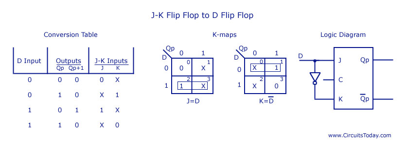
- D Flip Flop to JK Flip Flop
In this conversion, D is the actual input to the flip flop and J and K are the external inputs. J, K and Qp make eight possible combinations, as shown in the conversion table below. D is expressed in terms of J, K and Qp.
The conversion table, the K-map for D in terms of J, K and Qp and the logic diagram showing the conversion from D to JK are given in the figure below.