Master-slave JK flip-flop is designed to eliminate the race around condition in JK flip-flop and it is constructed by using two JK flip-flops as shown in the circuit diagram below.
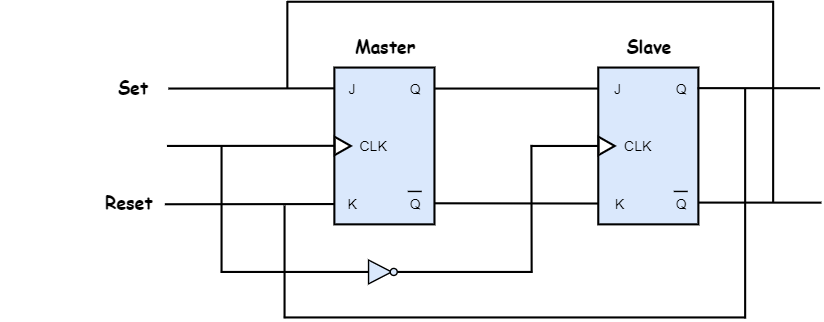
The first flip-flop is called the master, and it is driven by the positive clock cycle. The second flip-flop is called the slave, and it is driven by the negative clock cycle. During the positive clock cycle, master flip-flop gives the intermediate output but slave flip-flop will not give the final output. During the negative clock cycle, slave flip-flop gets activated and copies the previous output of the master flip-flop and produces the final output.
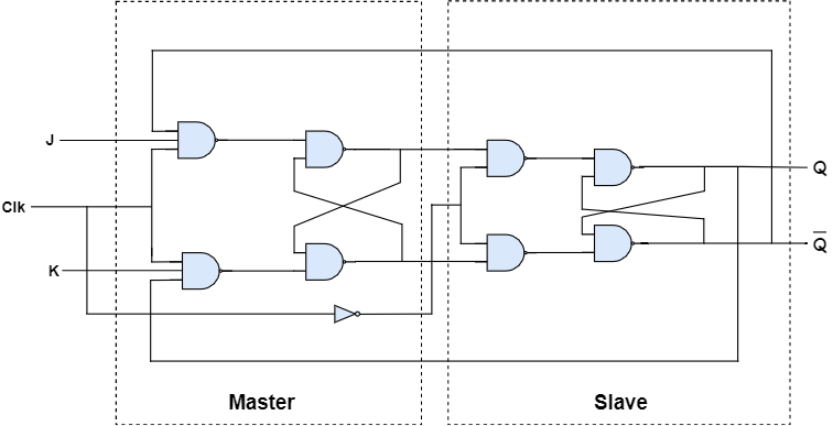
Master-slave JK flip-flop constructed by using NAND gates
State table
| Clock | J | K | Q(n+1) | Comments |
|---|---|---|---|---|
| 0 | X | X | Q(n) | No change |
| 1 | 0 | 0 | Q(n) | No change |
| 1 | 0 | 1 | 0 | Reset |
| 1 | 1 | 0 | 1 | Set |
| 1 | 1 | 1 | Q(n)’ | Toggle |
Here, Q(n) is the present state and Q(n+1) is the next state.
Characteristic table
| Q(n) | J | K | Q(n+1) |
|---|---|---|---|
| 0 | 0 | 0 | 0 |
| 0 | 0 | 1 | 0 |
| 0 | 1 | 0 | 1 |
| 0 | 1 | 1 | 1 |
| 1 | 0 | 0 | 1 |
| 1 | 0 | 1 | 0 |
| 1 | 1 | 0 | 1 |
| 1 | 1 | 1 | 0 |
Excitation table
| Q(n) | Q(n+1) | J | K |
|---|---|---|---|
| 0 | 0 | 0 | X |
| 0 | 1 | 1 | X |
| 1 | 0 | X | 1 |
| 1 | 1 | X | 0 |
No comments:
Post a Comment