Monday, October 14, 2019

Types of Shift Register


Note: Consider all Images with Negative edge triggering and update in your diagram accordingly.

SISO:


SIPO:


PISO:


PIPO:


Monday, September 23, 2019

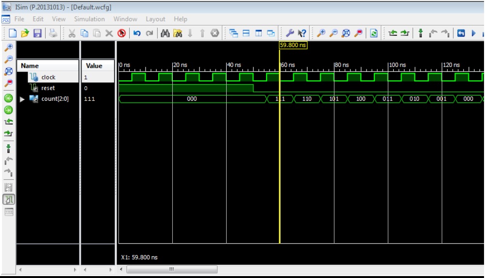
Write VHDL code for 3 bit Asynchronous up counter using Structural modeling

library IEEE;
use IEEE.STD_LOGIC_1164.ALL;

entity jk_ff is
Port ( j : in STD_LOGIC;
k : in STD_LOGIC;
clock : in STD_LOGIC;
reset : in STD_LOGIC;
q : out STD_LOGIC);
end jk_ff;

architecture Behavioral of jk_ff is
signal jk : std_logic_vector(1 downto 0) := "00";
signal qsig : std_logic := '0';
begin
jk <= j & k;
process(reset,clock)
begin
if (reset = '1')then
qsig <='0';
elsif (clock'event and clock = '1')then
case (jk) is
when "00" => qsig <= qsig;
when "01" => qsig <= '0';
when "10" => qsig <= '1';
when others => qsig <= not qsig;
end case;
end if;
end process;
q <= qsig;
end Behavioral;

--Step2. VHDL code for 3 bit Counter using structural modeling

library IEEE;
use IEEE.STD_LOGIC_1164.ALL;

entity counter_test is
Port ( clock : in STD_LOGIC;
reset : in STD_LOGIC;
count : out STD_LOGIC_VECTOR (2 downto 0));
end counter_test;

architecture structural_test of counter_test is

component jk_ff is
Port ( j : in STD_LOGIC;
k : in STD_LOGIC;
clock : in STD_LOGIC;
reset : in STD_LOGIC;
q : out STD_LOGIC);
end component;

signal temp:std_logic_vector(2 downto 0) := "000";

begin

label1 : jk_ffport map ( reset => reset, clock => clock, j => '1', k => '1', q => temp(2));
label2 : jk_ff port map (reset => reset,clock =>NOT temp(2), j => '1', k => '1', q => temp(1));
label3 : jk_ff port map ( reset => reset,clock => NOT temp(1), j => '1', k => '1',q => temp(0));
count(2) <= temp(0);
count(1) <= temp(1);
count(0) <= temp(2);

end structural_test;

--Step3. Test Bench Code

LIBRARY ieee;
USE ieee.std_logic_1164.ALL;
ENTITY tb_test1 IS
END tb_test1;
ARCHITECTURE behavior OF tb_test1 IS
COMPONENT counter_test
PORT(
clock : IN std_logic;
reset : IN std_logic;
count : OUT std_logic_vector(2 downto 0)
);
END COMPONENT;
--Inputs
signal clock : std_logic := '0';
signal reset : std_logic := '0';
--Outputs
signal count : std_logic_vector(2 downto 0);
BEGIN
-- Instantiate the Unit Under Test (UUT)
uut: counter_test PORT MAP (
clock => clock,
reset => reset,
count => count
);

process
begin
wait for 5ns;
clock <= not clock;
end process;

process
begin
reset <= '1';
wait for 50ns;
reset <= not reset;
wait;
end process;

END;

Sunday, September 22, 2019

Write VHDL code for Half Adder using Behavioral modeling

library IEEE;
use IEEE.STD_LOGIC_1164.ALL;

entity ha is
    Port ( a : in  STD_LOGIC;
           b : in  STD_LOGIC;
           sum : out  STD_LOGIC;
           cout : out  STD_LOGIC);
end ha;

architecture Behavioral of ha is
begin
process(a,b)
begin

if(a = '0' AND b ='0') then
sum <= '0';
cout <= '0';

elsif(a = '0' AND b ='1') then
sum <= '1';
cout <= '0';

elsif(a = '1' AND b ='0') then
sum <= '1';
cout <= '0';

else

sum <= '0';
cout <= '1';

end if;
end process;
end Behavioral;

Write VHDL code for Half Adder using Data Flow Modeling

library IEEE;
use IEEE.STD_LOGIC_1164.ALL;

entity test_HA is
Port ( a : in STD_LOGIC;
b : in STD_LOGIC;
sum : out STD_LOGIC;
cout : out STD_LOGIC);
end test_HA;

architecture data_flow_test of test_HA is
begin
sum<= a xor b;
cout<= a and b;
end data_flow_test;

Write VHDL code for 3 bit Asynchronous down counter using Structural modeling

--Step1. VHDL code for JK-FF

library IEEE;
use IEEE.STD_LOGIC_1164.ALL;

entity jk_ff is
Port ( j : in STD_LOGIC;
k : in STD_LOGIC;
clock : in STD_LOGIC;
reset : in STD_LOGIC;
q : out STD_LOGIC);
end jk_ff;

architecture Behavioral of jk_ff is
signal jk : std_logic_vector(1 downto 0) := "00";
signal qsig : std_logic := '0';
begin
jk <= j & k;
process(reset,clock)
begin
if (reset = '1')then
qsig <='0';
elsif (clock'event and clock = '1')then
case (jk) is
when "00" => qsig <= qsig;
when "01" => qsig <= '0';
when "10" => qsig <= '1';
when others => qsig <= not qsig;
end case;
end if;
end process;
q <= qsig;
end Behavioral;

--Step2. VHDL code for 3 bit Counter using structural modeling

library IEEE;
use IEEE.STD_LOGIC_1164.ALL;

entity counter_test is
Port ( clock : in STD_LOGIC;
reset : in STD_LOGIC;
count : out STD_LOGIC_VECTOR (2 downto 0));
end counter_test;

architecture structural_test of counter_test is
component jk_ff is
Port ( j : in STD_LOGIC;
k : in STD_LOGIC;
clock : in STD_LOGIC;
reset : in STD_LOGIC;
q : out STD_LOGIC);
end component;
signal temp:std_logic_vector(2 downto 0) := "000";
begin
label1 : jk_ff
port map ( reset => reset, clock => clock, j => '1', k => '1', q => temp(2));
label2 : jk_ff port map (reset => reset,clock => temp(2), j => '1', k => '1', q => temp(1));
label3 : jk_ff port map ( reset => reset,clock => temp(1), j => '1', k => '1',q => temp(0));
count(2) <= temp(0);
count(1) <= temp(1);
count(0) <= temp(2);
end structural_test;

--Step3. Test Bench Code

LIBRARY ieee;
USE ieee.std_logic_1164.ALL;
ENTITY tb_test1 IS
END tb_test1;
ARCHITECTURE behavior OF tb_test1 IS
COMPONENT counter_test
PORT(
clock : IN std_logic;
reset : IN std_logic;
count : OUT std_logic_vector(2 downto 0)
);
END COMPONENT;
--Inputs
signal clock : std_logic := '0';
signal reset : std_logic := '0';
--Outputs
signal count : std_logic_vector(2 downto 0);
BEGIN
-- Instantiate the Unit Under Test (UUT)
uut: counter_test PORT MAP (
clock => clock,
reset => reset,
count => count
);

process
begin
wait for 5ns;
clock <= not clock;
end process;

process
begin
reset <= '1';
wait for 50ns;
reset <= not reset;
wait;
end process;

END;

OUTPUT:

Write VHDL code for 4:1 MUX

library IEEE;
use IEEE.STD_LOGIC_1164.all;

entity mux_test is
port(
A,B,C,D : in STD_LOGIC;
S0,S1: in STD_LOGIC;
Z: out STD_LOGIC
);
end mux_test;

architecture beh_test of mux_test is
begin
process (A,B,C,D,S0,S1) is
begin
if (S0 ='0' and S1 = '0') then
Z <= A;
elsif (S0 ='1' and S1 = '0') then
Z <= B;
elsif (S0 ='0' and S1 = '1') then
Z <= C;
else
Z <= D;
end if;
end process;
end beh_test;

Test Bench Code for 4 to 1 Multiplexer:

LIBRARY ieee;
USE ieee.std_logic_1164.ALL;
ENTITY tb_mux_test IS
END tb_mux_test;
ARCHITECTURE behavior OF tb_mux_test IS
-- Component Declaration for the Unit Under Test (UUT)
COMPONENT mux_test
PORT(
A : IN std_logic;
B : IN std_logic;
C : IN std_logic;
D : IN std_logic;
S0 : IN std_logic;
S1 : IN std_logic;
Z : OUT std_logic
);
END COMPONENT;
--Inputs
signal A : std_logic := '0';
signal B : std_logic := '0';
signal C : std_logic := '0';
signal D : std_logic := '0';
signal S0 : std_logic := '0';
signal S1 : std_logic := '0';
--Outputs
signal Z : std_logic;
BEGIN
uut: mux_test PORT MAP (
A => A,
B => B,
C => C,
D => D,
S0 => S0,
S1 => S1,
Z => Z
);

process
begin
wait for 5 ns;

A <= '1';
B <= '0';
C <= '1';
D <= '0';

S0 <= '0'; S1 <= '0';
wait for 10 ns;

S0 <= '0'; S1 <= '1';
wait for 10 ns;

S0 <= '1'; S1 <= '0';
wait for 10 ns;

S0 <= '1'; S1 <= '1';
wait for 10 ns;

end process;
END;

OUTPUT:


Write VHDL code for JK Flip Flop

library IEEE;
use IEEE.STD_LOGIC_1164.ALL;

entity jk_ff is
Port ( j : in STD_LOGIC;
k : in STD_LOGIC;
clock : in STD_LOGIC;
reset : in STD_LOGIC;
q : out STD_LOGIC);
end jk_ff;

architecture Behavioral of jk_ff is
signal jk : std_logic_vector(1 downto 0) := "00";
signal qsig : std_logic := '0';
begin
jk <= j & k;
process(reset,clock)
begin
if (reset = '1')then
qsig <='0';
elsif (clock'event and clock = '1')then
case (jk) is
when "00" => qsig <= qsig;
when "01" => qsig <= '0';
when "10" => qsig <= '1';
when others => qsig <= not qsig;
end case;
end if;
end process;
q <= qsig;
end Behavioral;